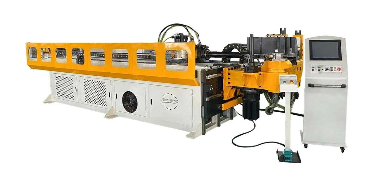
Now CNC Tube Bender technology is widely used in the electric power construction in our country, public and railway construction, boilers, Bridges, ships, furniture, household appliances and decoration and other industries, its process is also developing with the progress of modern technology.
First, the selection of displacement sensor
In the measurement and control system of CNC Tube Bender, displacement sensors need to be applied in many places to measure and detect the relevant displacement, such as the actual traveling displacement of Y-axis feeding, hydraulic control of advance and advance tool position, etc. Therefore, the selection of displacement sensors is particularly important. In the design of this system, the Hall type displacement sensor is mainly chosen, and the Hall sensor is briefly introduced in the following.
That is, when a current I is controlled at both ends of a metal or semiconductor sheet and a magnetic field with a magnetic induction intensity of B is applied in the direction perpendicular to the plane of the sheet, an electric potential U is generated in the direction perpendicular to the current and magnetic field. The Hall effect is the result of the moving charge being acted on by the Lorenan magnetic force in the magnetic field. The relationship between the Hall potential U generated and the control current J and the magnetic induction intensity B is as follows:
In order to improve the sensitivity of the Hall element, the Ph should be large and the d should be small. Because the Rh of semiconductors is much larger than that of metals, it is common to use semiconductors to make Hall components. It can be seen from the above formula that for a given Hall element (i.e., Ph is constant), if the control current is kept constant, the output voltage Uh can be changed only by changing the magnetic induction intensity B. The Hall displacement sensor changes Lr by changing the relative position of the permanent magnet and the Hall element, that is, changing the size of B, so as to realize the conversion between the displacement and the output voltage.
Second, the selection of rotary encoder
CNC Tube Bender rotary encoder is used to measure the speed of the device, photoelectric rotary encoder through photoelectric conversion, the output shaft angular displacement, angular speed and other mechanical quantities into the corresponding electrical pulse output (REP). It is divided into single output and double output two kinds. The main technical parameters are the number of pulses per revolution (dozens to thousands of them), and the power supply voltage. Single output means that the output of the rotary encoder is A set of pulses, and the dual-output rotary encoder outputs two sets of pulses with A/B phase difference of 90 degrees, through which the two sets of pulses can not only measure the speed, but also judge the direction of rotation. Encoders such as the signal principle can be divided into incremental pulse encoder :SPC and absolute pulse encoder :APC, both are generally used in speed control or position control system detection elements. The rotary encoder has A photocode disk with A central axis, on which there are annular and dark engraving lines, and photoemission and receiving devices to read, obtain four groups of sine wave signals combined into A, B, C, D, each sine wave phase difference of 90 degrees (relative to a frequency of 360 degrees), the C and D signals reverse, superposition on a and B two phases, can enhance the stable signal; Another Z-phase pulse is output per revolution to represent the zero reference bit.
Since the phase A and B differ by 90 degrees, the positive rotation and reversal of the encoder can be judged by comparing the A phase in front or the B phase in front, and the zero reference bit of the encoder can be obtained by the zero pulse. The encoder has 5 leads, 3 of which are pulse output lines, 1 is COM terminal line, and 1 is power line (OC gate output type). The power supply of the encoder can be an external power supply, or the DC24V power supply of the PLC can be used directly. The "-" end of the power supply is connected to the COM end of the encoder, and the "+" end is connected to the power end of the encoder. The COM end of the encoder is connected with the PLC input COM end, A, B, Z two-phase pulse output line is directly connected with the PLC input end, A, B is the pulse of 90 degrees difference, Z believes that there is only one pulse in the encoder rotation, usually used as the basis for zero, connection should pay attention to the PLC input response time. The rotary encoder also has a shielded line, which should be grounded when used to improve anti-interference. Resolution - The number of pass or dark lines provided by the encoder per 360 degrees of rotation is called resolution, also known as analytical division, or directly called how many lines, generally 5 to 10000 lines per revolution. 2 Incremental and absolute rotary encoder The incremental encoder directly uses the photoelectric conversion principle to output three groups of square wave pulses A, B and Z phase; The phase difference between group A and group B is 9O. When the rotating shaft of the incremental encoder rotates, there is a corresponding pulse output, and the counting starting point is arbitrarily set, which can realize infinite accumulation and measurement of multiple turns. A rotation of the encoder shaft will output a fixed pulse, and the number of pulses is determined by the number of lines of the encoder grating. When you need to improve the resolution, you can use the 90 degree phase difference A and B signals to double the frequency or replace the high resolution encoder. There are many lines on the absolute encoder code disc, and each line is sequentially divided into 2 lines, 4 lines, 8 lines, 16 lines... The arrangement is so that at each position of the encoder, by reading the pass and dark of each line, a set of unique binary codes (Gray code) from 2 to the zero power to 2 to the n-1 power are obtained, which is called the n-bit absolute encoder. Such an encoder is determined by the mechanical position of the code disc, which is not affected by power outage and interference.
The uniqueness of each position determined by the mechanical position of the absolute encoder, it does not need to remember, do not need to find a reference point, and does not have to count all the time, whenever it needs to know the position, when to read its position. In this way, the anti-interference characteristics and data reliability of the encoder are greatly improved [12]. In the actual production process, considering that the absolute encoder cost is much higher than the incremental encoder, the CNC Tube Bender measurement and control system adopts the incremental rotary encoder, and the resolution is selected as 3600 lines according to the production practice, so as to meet the accuracy requirements of the minimum resolution of the system of ±0.1°. The measurement and control system adopts the HEDSS rotary encoder, ISC4406 series, the output pulse is 3600P/R, 5L.
CNC Tube Bender https://www.john-sheng.com/CNC-Tube-Bender